V. Analytical Modeling of Terminal Ballistics
V. A. Introduction
I enjoy analysis, and ever since I have been interested in firearms I have been actively searching for theoretical models for interior, exterior and terminal ballistics. I soon discovered that accurate models for both interior and exterior ballistics have been available for some time. The Powley computer calculates optimal loads based on the IMR series of powders for specific cartridge capacities and pressure constraints and gives you a predicted velocity. Several exterior ballistics models are available in software packages compatible with PCs and I was able to write a very satisfactory one for myself using a 4th order Runge-Kutta numerical integration based on the information provided at the rear of my Sierra reloading manuals and published drag data. However, no one had a generally accepted model for terminal ballistics. The chief reason for this dearth of analytical joy is that there is no consensus on how to quantify terminal performance - or even on the phenomena contributing to wounding potential!
This is surprising because such things have been available in the military sector for many years and are used to calculate the penetration of shaped charge jets and long rod penetrators through different armors. This, in spite of the fact that the mechanics of lethality, as distinguished from penetration mechanics, are debated in the military sector just as in the firearms community. If the firearms community could agree that it is the hole which counts (at least as a first order approximation of relative lethality), then something of this nature could be made applicable. The drawback to these defense penetration models, of course, is that they are extremely complicated and require great computational power to run. Something more readily available and understandable to the average shooter is what is needed.
V. B. Fidelity in Modeling
Experiments described in the preceding section on methods of experiment demonstrate several things about the terminal performance of bullets:
Any model which attempts to predict bullet penetration and cavitation must account for these observations. An understanding of what is taking place is a necessary starting point for developing a realistic model. In non-hydrodynamic (non-deforming) penetration, the depth of penetration and cavity diameter are a linearly increasing function of velocity, since bullet diameter and mass are constant (note that the tissue in the target is in hydrodynamic flow until penetration stops). For deforming bullets, there is an initial phase of penetration in which no deformation occurs. This is usually termed the upset distance. Deformation occurs suddenly due to pressures exceding the flow stress of the bullet. The penetration of the upset distance is a reflection of the resistive forces (molecular friction) within the bullet. The hydrodynamic (deforming) penetration phase is very brief and at the conclusion of this phase the bullet will have traveled only a short distance. The stronger the bullet, the longer a distance it will travel while it deforms. Correspondingly, at higher velocities a bullet will travel a shorter distance as it deforms due to more rapid deformation. The final phase of penetration is non-hydrodynamic, starting at the threshold critical velocity, and accounts for most of the penetration and cavitation of a bullet. This explains why a deforming bullet has a nearly constant penetration over a wide range of impact velocities and frequently a diminishing penetration with increasing velocity. Penetration terminates when the velocity reaches a point where the flow stress of the tissue exceeds the stagnation pressure of the penetration. Elastic penetration may occur at this stage, wherein the bullet travels forward some distance before the tissue returns to its original position. This is similar behavior to temporary cavitation but occurs in the axial direction and is most commonly recognized in a bullet being found "lodged under the skin" on the far side of an animal.
V. C. A Simple Analytical Model of Bullet Penetration
When I first published this webpage, I did not include the following discussion on the site itself because I thought it was too complex and would not be of interest to most readers, but I include it now rather than in an attached paper.
Relatively simple two-dimensional axisymmetric expressions of mechanics can be used to model the penetration and crater development (permanent cavity) of a deforming bullet in tissue. In the discussion that follows, certain assumptions are maintained:
There are two distinct phases of behavior for a deforming bullet during a penetration event. In the first, called the hydrodynamic penetration phase, the bullet is subject to plastic deformation under the pressure felt at its interface with the tissue in the target. Material is eroded at the bullet tip, causing outward and rearward flow of metal, or mushrooming, and/or there is fragmentation. In the latter phase, called the rigid-body penetration phase, the bullet has ceased to deform plastically and penetrates without further change in shape or loss of mass. Different mechanical expressions are used to describe these two phases.
V. C. i. The Alekseevski-Tate Equations of Penetration
A physically accurate analytical model of the mechanics of hydrodynamic penetration was independently developed in the mid-1960s by Soviet researcher V. P. Alekseevski and also by British defense scientist A. Tate of the Royal Armament Research and Development Establishment (RARDE), in the context of long rod penetration of armor. Tate's analysis was first published in A Theory for Deceleration of Long Rods After Impact (November 1967, Journal of the Mechanics and Physics of Solids, Vol. 15, Issue 6, pgs. 387-399). Tate continued his research to expand on his initial theory well into the 1980s and has been followed by researchers at Army Research Laboratory (ARL) and other establishments since that time. I have included a list of useful references at the bottom of this page. I had the good fortune and pleasure of a professional relationship over a decade with Bill Walters of ARL, who is co-author on several of the papers cited.
The model assumes a homogeneous cylindrical rod of constant diameter and uniform mechanical properties as projectile, impacting a semi-infinite homogeneous target. The typical case for these analyses is a tungsten or depleted uranium rod impacting steel. However, the analytical solution is universal. It accurately describes the behavior of hydrodynamic penetration for all cases.
The governing equations of penetration developed by Alekseevski and Tate are:


Immediately, we see some important observations regarding hydrodynamic penetration. Most strikingly, penetration depth does not depend on expanded diameter of the projectile. Since it is hydrodynamic flow, it obeys Bernoulli's Law and depends only on the penetration velocity, which is (we will see) a function of the projectile velocity and on the mechanical properties of flow stress (strength) and density of the projectile and target. Expanded diameter does affect the crater (cavity) diameter, but that is a second order effect that we will examine separately. The mass of the projectile also does not affect the penetration depth during this phase. Length of the projectile, however, is of critical importance.
The principal expressions of the penetration mechanics in this method are analytical, which is a great strength of the method. Since the Alekseevski-Tate equations are well supported by analytical and empirical evidence, we may use them with confidence, and since the rigid body mechanics (described hereafter) do depend explicitly on the kinetic energy using residual projectile mass and the known velocity at the termination of hydrodynamic penetration, the results should be very good. Using analytical models of rigid body penetration mechanics for non-hydrodynamic penetration also accounts for inertial and viscous drag forces, material failure conditions, and strength effects at low velocities.
The method described here does not explicitly account for the significant energy expended by bullet deformation and mass loss. However, the effect of these behaviors may be described by using a separate set of functions to calculate variables such as expanded diameter and retained mass as a function of the residual length of the bullet based on empirical data. This technique allows us to adapt the Alekseevski-Tate equations from the case of a homogeneous rod of constant diameter to the case of a jacketed bullet composed of two or more metals in a complex shape by using a composite density and yield strength based on an area weighted function of these quantities for each cross-section of the bullet.
Numerical integration is performed in both phases in terms of decaying projectile velocity, a convenient quantity.
V. C. ii. Hydrodynamic (Eroding Projectile) Penetration
Since the parameter that we wish to use for numerical integration is projectile velocity and further since we don't know how the penetration proceeds as a function of time, we need to eliminate time as a variable.
From the foregoing Alekseevski-Tate equations, we may observe that,

Therefore,

Resultantly, the differential projectile length and the differential penetration, both as functions of projectile velocity, are given by:

However, in order to evaluate the above expressions, we also need to calculate the penetration velocity, which can be derived from the first of the Alekseevski-Tate equations (the derivation is complicated and will not be shown here). Solving for penetration velocity in terms of projectile velocity yields:

The term γ in the above expression for penetration velocity is taken from the Bernoulli equation for fluid flow that governs true hydrodynamic penetration. Note: There are other derivations of the penetration velocity that are algebraically equivalent, but that may yield a different result because of sensitivity to negative values in the root term. This expression seems the most stable in numerical analyses.
Hydrodynamic flow conditions for the projectile cease at a velocity threshold such that the penetration velocity equals the velocity of the rear portion of the projectile. In other words, the entire projectile is now moving with uniform velocity, so erosion (deformation) has ceased, and it behaves as a rigid body from this point on until penetration terminates.

Note that the form of the above relation is only valid where the strength of the projectile is greater than that of the target. There is a similar corresponding expression for the obverse condition.
V. C. iii. Non-Hydrodynamic (Rigid Body) Penetration
After the termination of hydrodynamic penetration, the projectile continues to penetrate as a rigid body. Probably the oldest and still one of the best analytical expressions of rigid body penetration mechanics was derived in the mid-19th century by the father of penetration mechanics, French engineer Jean-Victor Poncelet. Using Newton's basic expression of mechanics as a beginning point, Poncelet proposed that the opposing forces that caused a bullet to decelerate were a static retarding force and a dynamic retarding force that is a function of the velocity of penetration, of the form:

Experiment has demonstrated that the quasi-static resistive force is that required to create a stress state in the target material sufficient to bring it to yield or flow condition. Tissue is not a true fluid; it is a solid and has strength. This material crushing force is proportional to the flow stress of the target medium (yield condition) and the presented area of the expanded projectile. If you examine the following expression, you will note that it is a constant.

The dynamic drag force is that required to overcome the fluid resistance in the crushed target material and push through. The dynamic drag force is described using a basic fluid mechanics model expressing flow dynamic pressure multiplied by presented area, as follows:

Because the Reynolds number is used to calculate the drag coefficient, both inertial and viscous drag forces are represented in the dynamic drag force. In practice, the inertial drag forces dominate the problem. Even for small bullets at very low (termination) velocities, the Reynolds number will be greater than 100, so the boundary layer is small and laminar flow is not the dominant behavior.
For a typical expanded bullet, the drag coefficient for a sphere or hemisphere can be used. Alternatively, the drag on a hollow hemisphere (open downstream) might be better still. For these ballistic events, the Reynolds number falls within the range of 5000 to 50,000. Across this range the drag coefficient for a smooth hemisphere shape typically falls between 0.4 and 0.5 and can be treated as a constant or allowed to be a variable and calculated as a function of velocity.
According to Cranz' Law, the cavitated volume of penetration is proportional to the kinetic energy and inversely proportional to the resistive forces acting on the penetrator. During non-hydrodynamic penetration, all the kinetic energy expended is converted into work causing the cavitation (i.e., no work is being done on the projectile).
Using this principle, the combined forces acting on the projectile can be resolved into the following expression for differential rigid body penetration:

V. C. iv. Elastic Limit Velocity
Elastic limit is the velocity at which the dynamic pressure equals the yield stress of the target material. The elastic limit velocity determines the lower limit of penetration. Below this penetration velocity and until the projectile comes to rest, the target material responds elastically, no plastic deformation occurs and no permanent penetration cavity is created.

V. C. v. Permanent Cavity Diameter
There have been numerous proposed analytical expressions of crater formation for eroding rod and rigid body penetration, using the momentum balance or the energy balance at the penetration interface. Most of these methods consider the target material strength and some also include secondary flow of the target material. These expressions were developed in the context of armor penetration, in which the target material exhibits very high strength relative to the penetrator, and they often do not adequately treat the condition of non-hydrodynamic crater formation, which comprises a significant portion of wound ballistic penetration events.
The following expression is adapted from the Held equation for permanent crater dimensions in shaped charge jet penetration:

The above relation produces estimates of hole diameter during non-hydrodynamic penetration that are in good agreement with the very complex method devised by Lee and Bless for long rods. When simplified by eliminating terms that become zero in non-hydrodynamic penetration, the Lee-Bless equation for permanent cavity diameter (adapted to this context) becomes:

I find the Held equation to be more useful because it better describes the hydrodynamic behavior for bullet cavitation than the Lee-Bless equation and is far less complex.
V. C. vi. Derivation of Target Resistance
Target resistance, R, is the flow stress required to overcome inertial and strength forces to create a cavity in a material. The value lies somewhere between the static yield strength under standard conditions and the maximum physical limit of the material sound speed at pressure defined by the Hugoniot. It was derived by Bishop, Hill and Mott as:

V. D. Example Results of the Analytical Model
Because it had been over twenty years since I first published this page, I went through all of the derivations for the Alekseevski-Tate equations and the non-hydrodynamic penetration equations by hand again in 2022. The original implementation that I did many years ago using Fortran (I know, that dates me) cannot now be easily executed. The last Fortran compiler I had was a Microsoft Powerstation that I pulled out of the company trash back around 2004 and it probably won't run on any computer still extant. So, I turned to the same answer that I used to update my exterior ballistics calculator back in 2010: Microsoft Excel. Any similar spreadsheet should work as long as it allows math functions. While it may seem daunting, anyone with a decent grounding in science and high school calculus could write a simple numerical integration of these basic equations using MS Excel to get similar results to mine. There are some tricks of model development that will prevent instability and I will address that later.
As alluded to in the previous section, the goal of this exercise in analytical methods is to translate the general behaviors of hydrodynamic and non-hydrodynamic penetration into a model that will predict the performance of a specific bullet or bullet type of prescribed characteristics. What real use is it to compare hypothetical bullets? As such, the difficult part of the analysis is not the penetration mechanics, but rather in defining the expressions which will describe the process of bullet deformation because this drives the whole event. There are a lot of things going on, including changes in diameter and jacket thickness, strain hardening and failure, which simple analytical expressions do not address well. What follows is my best effort so far.
The secret to making any analytical model really useful is using input parameters that allow you to truly compare specific bullets of a particular design and construction and manufacture. So, unfortunately, any analytical model needs empirical data, that is, test data. Now, as it turns out a few manufacturers have occasionally provided some such data, at least in gross terms. I gathered some information from the published photos of the Swift Scirocco and also from the North Fork Technologies bullets. Both give you expanded diameters and eroded lengths as a function of impact velocity. What is missing for the Scirocco is the retained weight, but you can sometimes get that kind of information from other sources. To be used in a model like this one, you also need the metallurgical data and in that regard, I had to make some assumptions, particularly related to work hardening. A fair amount of trial and error is required, but you can adjust the parameters until you see the model reflect the test results. We have to do this sort of calibration with any analytical model.
Figure 1 below is an example of a plot of expanded diameter as a function of deformed length (which is a primary variable in the model and itself a function of impact velocity), made from data for a bonded core bullet. Never mind what brand, weight, style of bullet - this is for illustrative purposes. I did this with Microsoft Excel and you can see the third order polynomial function that was found by the regression algorithm. This is a very good fit. Sometimes, it is not nearly so good and looks more like a roller coaster. In such cases you may need to artificially smooth the data or get yourself a better regression solution or even try a piecewise curve fit. When it comes to model development there are many ways to skin a cat. I like this approach because I can create an input deck and just read coefficients A, B, C and D of a polynomial of the form Ax3 + Bx2 + Cx + D. Note that the curve reaches a maximum and then decreases. You observe this kind of behavior in many bullets as the impact velocity increases.
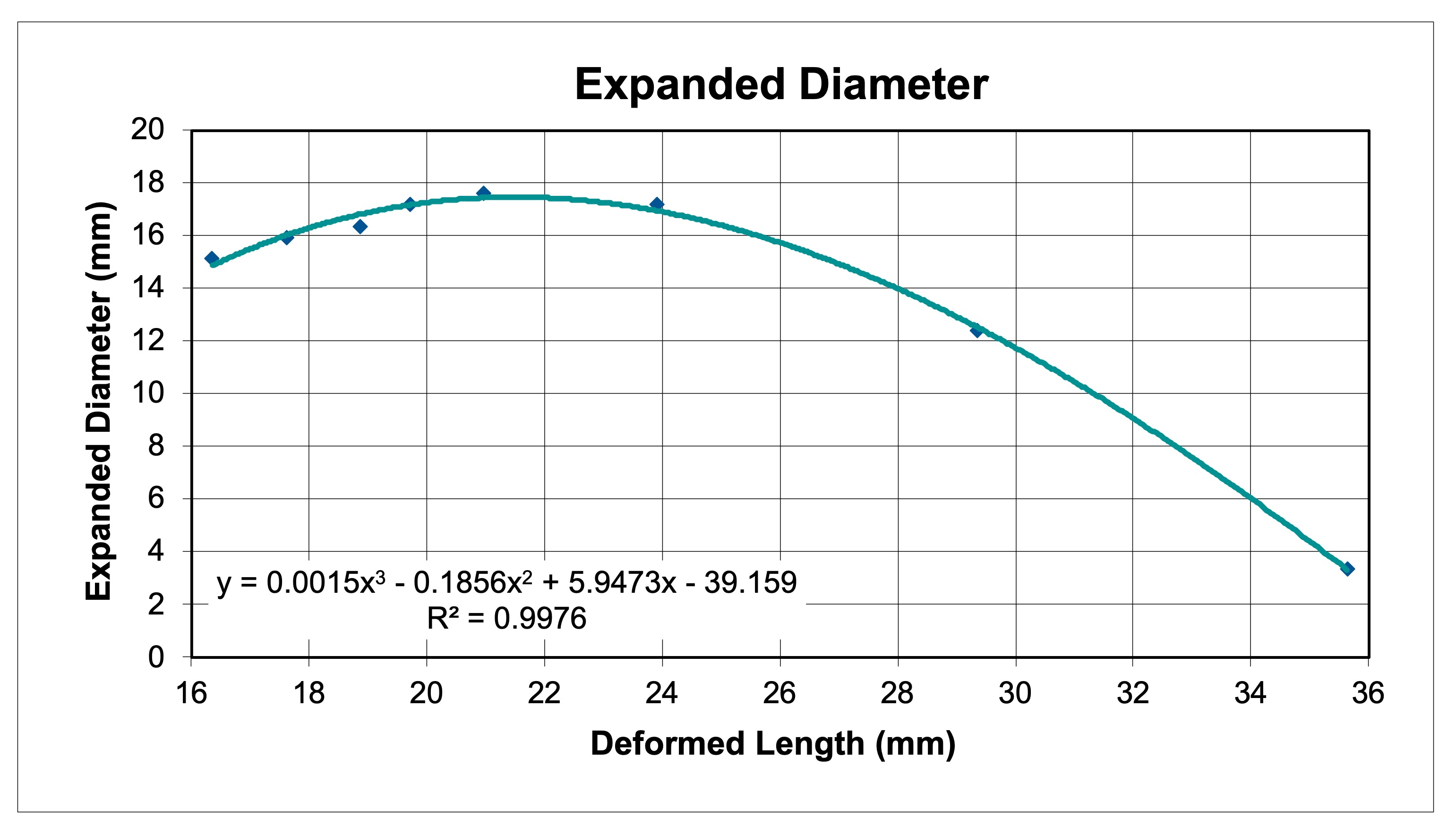
Figure 1: An Example Plot of the Function for Bullet Expansion
Figure 2 shows a similar plot for the function of retained weight as a function of deformed length. The original curve fit looked like a roller coaster. If you look at the data points it doesn't behave like that, but this was the closest fit that the Excel regression algorithm could achieve. This one isn't too awful. Its usable, but you're starting to introduce some error (retained weight obviously does not increase as the bullet deforms). An inflection point (or two) like this can introduce instability in a model, preventing convergence. That's where tricks come into play to keep the thing from going open-loop (like IF-THEN statements to preclude negative values, etc.).

Figure 2: An Example Plot of the Function for Bullet Retained Weight
Figure 3 below is an example data table for the mechanical properties of the bullet from the tip to the base. This is where you capture things like the changing diameter of the bullet (the Tate equations assume a rod of constant diameter), variations in jacket thickness and variations in jacket hardness. This is important in calculating the expressions for composite density and yield strength as a function of deformed length, shown below as Figures 4 and 5.

Figure 3: An Example Table of the Input Data for Mechanical Properties
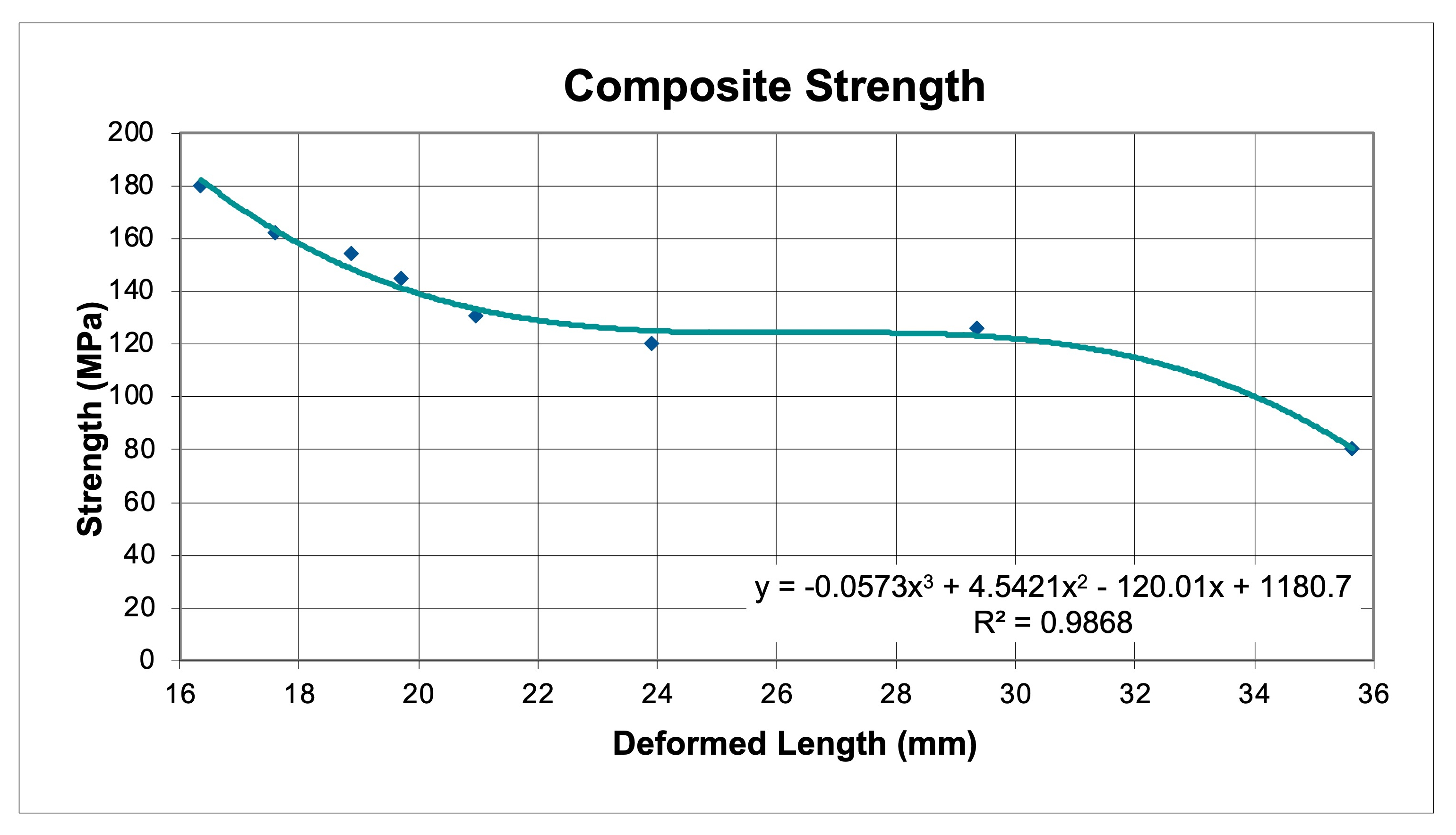
Figure 4: An Example Plot of the Function for Bullet Composite Yield Strength
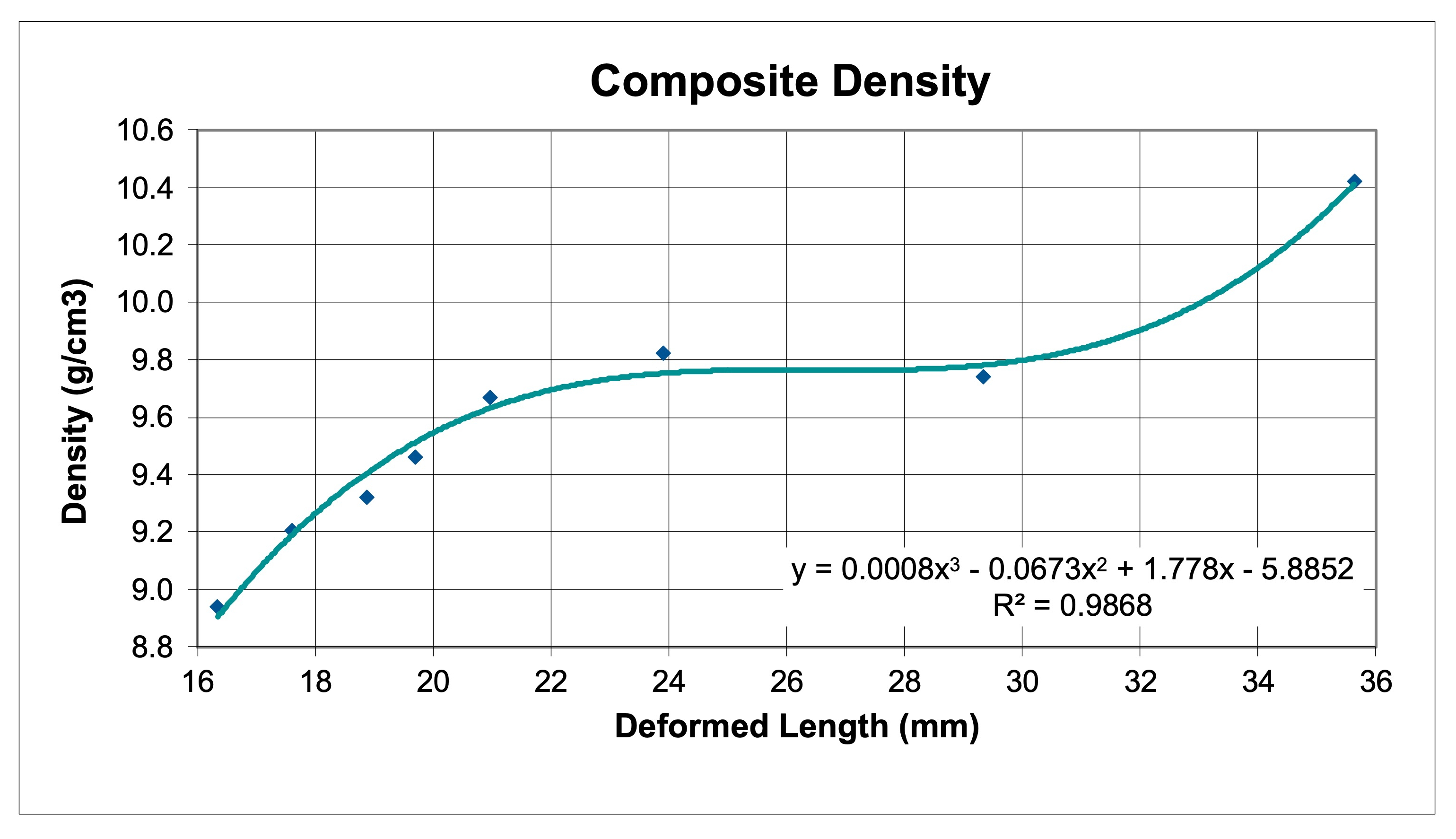
Figure 5: An Example Plot of the Function for Bullet Composite Density
Figure 6 depicts the validation of model prediction against actual measured bullet deformation of a Swift Scirocco. By this means one can adjust jacket and core strength values until model behavior agrees with test results.
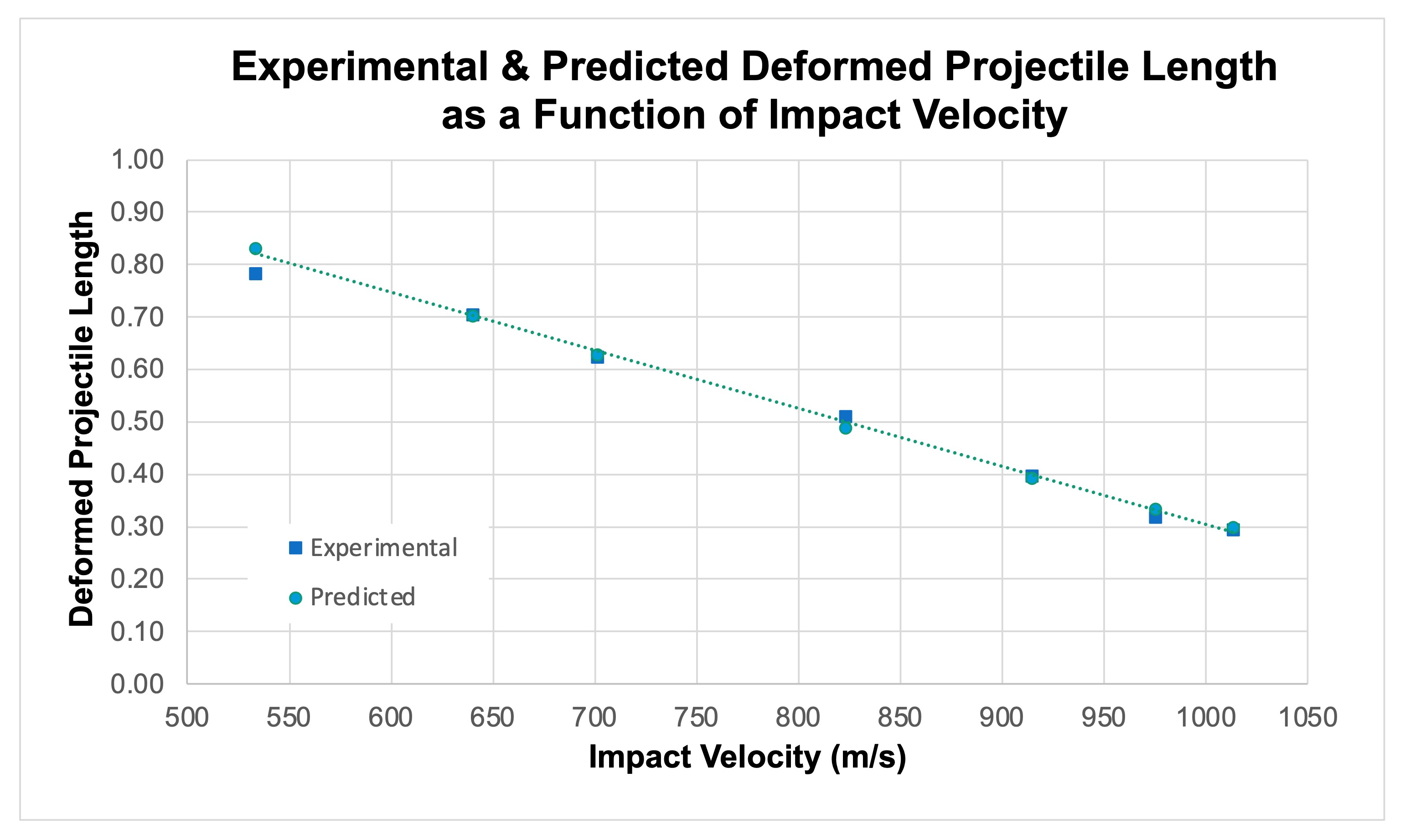
Figure 6: An Example Plot of the Validation of Bullet Parameters
The following plots illustrate some representative results from the model using these techniques for four types of .308 caliber 200 grain bullets.
Figure 7 illustrates the sort of results that you will get for this model at three representative velocities when parameters appropriate for a bullet of conventional swaged tube and core design and soft metallurgy is modeled; in this case a Hawk RT with a relatively thin 0.025 inch jacket. As we noted in the wetpack testing, the penetration depth varies over a surprisingly narrow range. Also note the very large expansion of the wound and rapid termination.
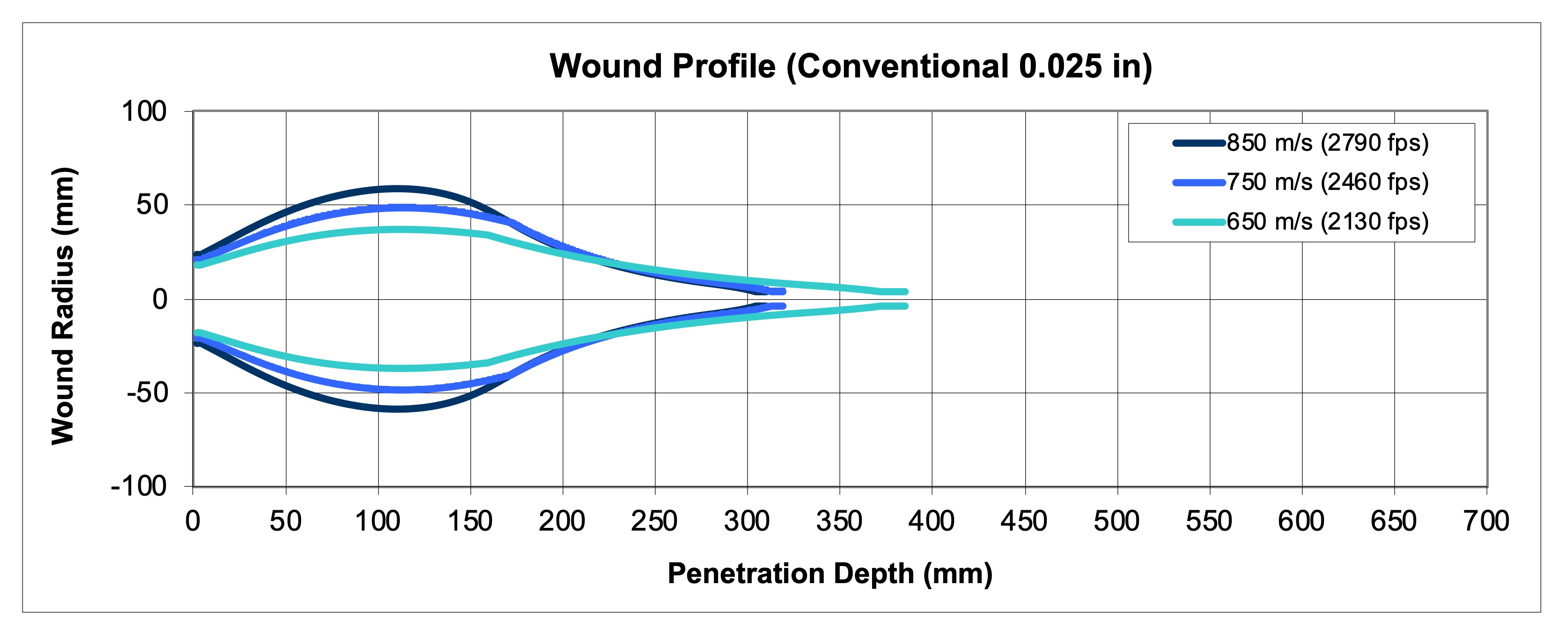
Figure 7: An Example Plot of the Wound Profile for a Conventional Bullet
Figure 8 shows a similar plot, this time for a swaged copper tube and lead core bullet with a heavier 0.035 inch thick jacket, but otherwise identical design features to the previous set of parameters. It achieves slightly more penetration at typical velocities, but significantly greater penetration and appreciably reduced maximum wound diameter as the velocity approaches the minimum upset velocity. This is the sort of traditional soft copper and lead design that performs so well in classic cartridges of modest velocity. You can most clearly see that penetration steadily decreases with increasing impact velocity in this plot.
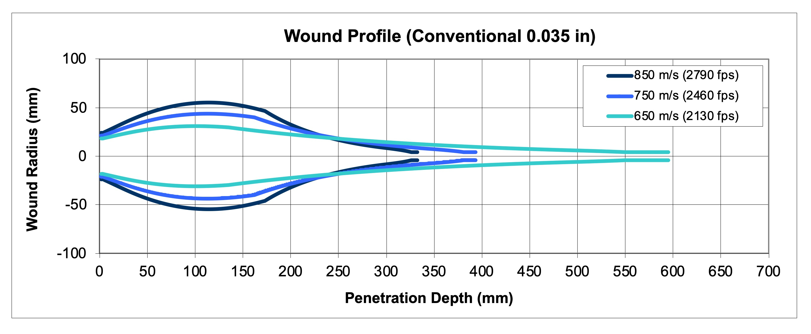
Figure 8: An Example Plot of the Wound Profile for a Conventional Bullet
This next plot (Figure 9) is representative of the sort of behavior that you would see with a more modern jacketed bullet of complex design and metallurgy. I based the model inputs on a North Fork Heavy Game 200 grain semi-spitzer. It has a thin, tapered jacket at the tip for rapid expansion, but rapidly thickens to limit expansion. Additionally, it can only deform to a fixed length and the expanded diameter is well supported, so that it maintains a larger wound profile at depth in the target. Note how closely the higher velocities match in total penetration (582 mm and 562 mm). The lowest velocity is not far behind with 465 mm. By tuning the jacket thickness and metallugy one can move the depth at which the maximum expansion occurs and also control the diameter of that expansion. Although it is obscured, in this data the penetration is deepest in the middle range of impact velocity, consistent with most tests of controlled expansion bullets. This is the behavior of a bullet of nearly constant expanded diameter.
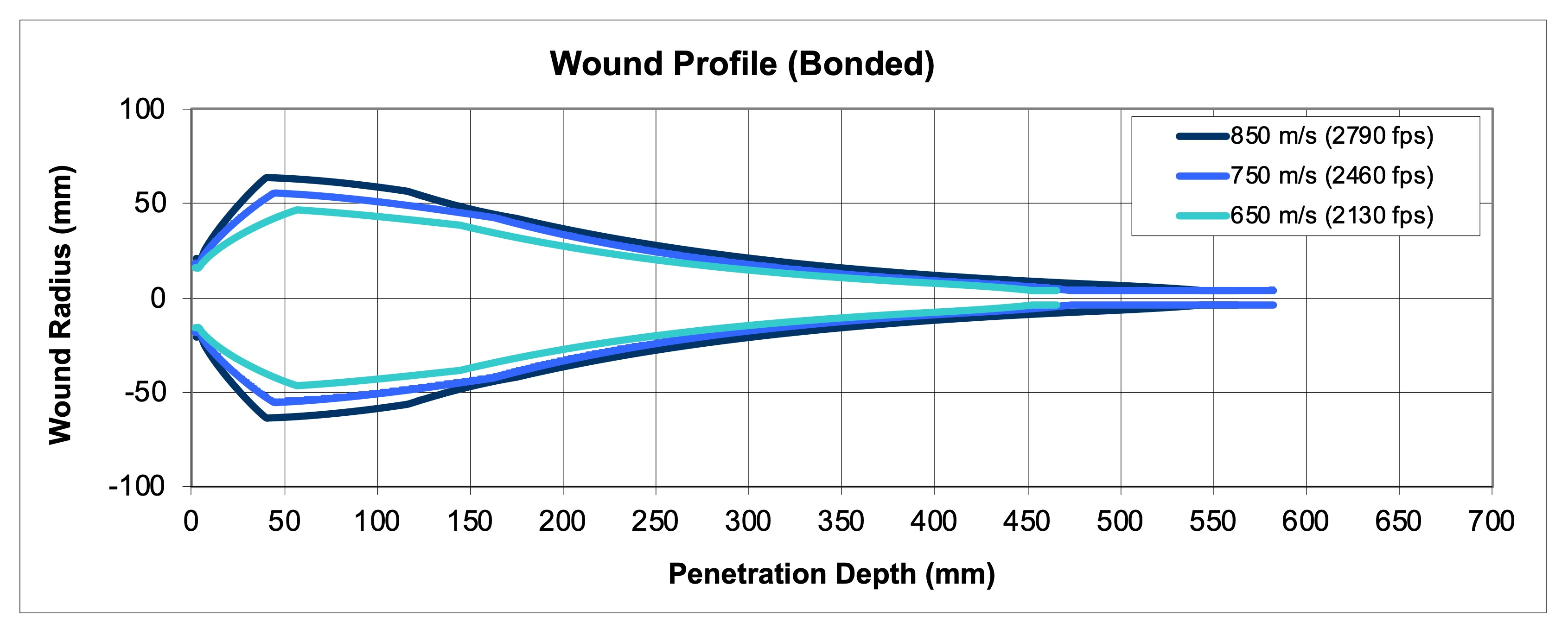
Figure 9: An Example Plot of the Wound Profile for a Bonded Core Bullet
Finally, in Figure 10, we have the classic behavior of a monolithic style of bullet (specifically, the original Barnes X-Bullet). Note that I did not attempt to model the petal shearing at high velocity. You could do that, though. It achieves the greatest depth of penetration and exhibits the narrowest, most nearly uniformly tapering wound profile. This class of bullet reminds me very much of the most advanced form of shaped charge now in existence in its economy of penetration. Here the penetration depth is greater at the lower and higher impact velocities, as we see in testing. This is the behavior of a bullet of modest expanded frontal area that varies with impact velocity. It is also the sort of trend you see with a premium bullet like the Nosler Partition in smaller calibers and the Speer Grand Slam because the expanded mushroom is severely swept back at higher impact velocities.

Figure 10: An Example Plot of the Wound Profile for a Monolithic Bullet
While none of these plots represents a validated model of any particular bullet (even though I used actual test data as much as possible), they serve to illustrate that the model gives us the distinct behaviors of different design features and metallurgical properties. In short, the model replicates reality to a reasonable degree and if one has metallurgical data and design geometry in hand, a close approximation of the real world performance can be calculated.
V. E. Model Limitations
There are obvious criticisms that may be leveled against the model I have presented here. Arguments might be raised against the Alekseevski-Tate analytical relations used in this application, but all I will say to this is that these approaches have been used with excellent accuracy in the defense sector for some time and I think can be used here with the techniques I describe. Are they the final word on small arms penetration mechanics? No, but they work.
At every step of the event, I have been forced to rely on a separate analytical model for permanent hole dimensions. The linear force-balance approach is quite incapable of providing this insight (without a dynamic finite element stress analysis) and it was a necessary input to the energy method that was employed in the rigid body phase of penetration.
The method described does not explicitly account for the partitioning of the kinetic energy between elastic and plastic strain in cavitation, however, the Held equation is probably very accurate for all but the region near the termination point (elastic limit velocity).
Similarly, I have applied no constitutive models for the mechanical properties of the materials in the bullet or target, but there is nothing inherent in the method to prevent this, if one has a good model (such things are also strongly empirical in derivation and if you want strain hardening behavior, then the Hopkinson bar test data used needs to be in the same strain rate regime). The approach that I used is far simpler for the average person to implement because you can get your own data from wetpack tests.
This model also fails to describe the upset distance because I don't have any relationship for the inertial effects of plastic strain, but in practice this phase of penetration is very short and has very little bearing on the overall analysis for bullets that are designed to expand (the same cannot be said of full metal jacketed bullets or match bullets that are not intended to deform, but an analysis of these types of bullets lies outside the scope of the problem as laid out in the constraining assumptions).
If anyone reading this is disgusted with my notion of a "simple" model of bullet penetration, understand that much of my motivation for developing and publishing this model was to illustrate just how difficult it is to accurately estimate real performance. This is why the kinds of shortcut calculations we've all seen fall flat when you get to specifics. I hope that anyone who has persevered to this extent can now appreciate why I have emphasized that simplistic answers are not meaningful, and tend only to reinforce generalizations that we knew already - or biases that may not be true.
V. F. References
A. Tate, Royal Armament Research and Development Establishment (RARDE), Fort Halstead, Sevenoaks, Kent
Journal of the Mechanics and Physics of Solids, Vol. 15, 1967, pgs. 387 - 399
William P. Walters and Steven B. Segletes, U.S. Army Ballistic Research Laboratory (BRL), Aberdeen Proving Ground
International Journal of Impact Engineering, Vol. 11, No. 2, 1991, pp. 225 - 231
Minhyung Lee and Stephan Bless, Institute for Advanced Technology (IAT), The University of Texas at Austin
IAT.R 0094, January 1996
Steven B. Segletes and William P. Walters, Army Research Laboratory (ARL)
ARL-TR-2855, September 2002
William Walters and Cyril Williams, Army Research Laboratory (ARL)
ARL-TR-3606, September 2005
W. Walters and C. Williams, US Army Research Laboratory, Terminal Effects Division, AMSRD-ARL-WM-TC, APG, MD
M. Normandia, Ceradyne, Inc., 3169 Red Hill Avenue, Costa Mesa, CA
International Journal of Impact Engineering, Vol 33, 2006, pgs. 837 - 846
Charles E. Anderson Jr., CEA Consulting, San Antonio, TX
International Journal of Impact Engineering, Vol 108, 2017, pgs. 3 - 26
Charles E. Anderson Jr., CEA Consulting, San Antonio, TX
International Journal of Impact Engineering, Vol 115, 2018, pg. 120
W. J. Jiao, Department of Modern Mechanics, University of Science and Technology of China, Hefei and Institute of Systems Engineering, China Academy of Engineering Physics, Mianyang
X. W. Chen, Advanced Research Institute for Multidisciplinary Science and the State Key Lab of Explosion Science and Technology, Beijing Institute of Technology, Beijing
Acta Mechanica Sinica, Vol 34, No. 2, 2018, pgs. 334 - 348
Continue on to:
VI. The Politics of Terminal Ballistics
Return to:
Contents
Mail to: Ulfhere at Rathcoombe.net Copyright 1999 - 2023 -- All Rights Reserved